|
技术中心 Protecting PV systemsBenefits of Circuit Protection Solutions
Unmatched Global OfferingWe offers a range of solar products with ratings up to 1000Vdc as well as UL, IEC and CCC certifications specific for PV applications― ensuring fully supported and seamless global installations. Legacy of Technical ExpertsWe are the experts in safe system design and application. Our R&D and Testing Laboratories are dedicated to protecting your system, from specification to delivery. Our Lab is one of the industry’s most comprehensive testing facilities, and is available to test your systems to global agency standards. Safe. Reliable. CompleteThe unique nature of PV system power generation necessitates the need for new and effective electrical protection products for overcurrent, overvoltage and isolation events. With a protected electrical system, you can optimize your renewable energy power generation capacity, knowing your equipment is safe. We are a single source for the entire AC and DC circuit protection and disconnecting means. We work closely with solar equipment manufacturers and, through coordinated research and development, have produced revolutionary new fuses offer complete protection for PV systems.
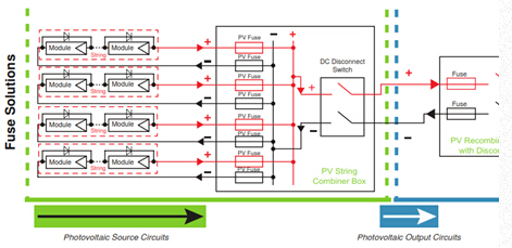
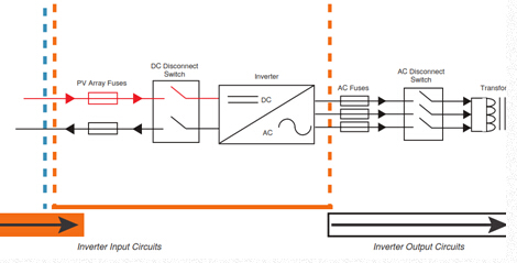
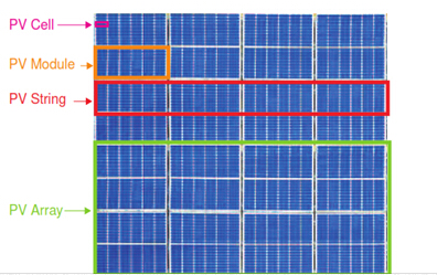
How PV systems workPV Cells are made from semi-conductor materials, such as polycrystalline silicon or thin film, that convert the sun’s light into DC electricity. PV Cells are connected in series to create a PV module and increase voltage. PV powered distribution network with NEC defined circuits designated by arrows
PV Modules are then connected in series to create a PV string and further increase voltage.
PV Systems standards
Unlike typical grid connected AC systems, the available short-circuit current within PV systems is limited, and the overcurrent protective devices need to operate effectively on low levels of fault current. For this reason, We has conducted extensive research and development of PV fuses that are specifically designed and tested to protect PV systems with high DC voltages and low fault currents. The International Electrotechnical Commissions (IEC) and Underwriters Laboratories (UL) recognize that the protection of PV systems is different than conventional electrical installations. This is reflected in IEC 60269-6 (gPV) and UL 2579 for fuses. PV Fuses- Fully tested to the requirements of IEC 60269-6 and exceed the requirements of operating at 1.45 x I (1.45 times the nominal current). They also meet the requirements of UL 2579 that are very similar to the IEC standards, except they operate at 1.35 x I (1.35 times the nominal current). - The current ratings assigned to PV fuses are defined by the performance requirements of IEC 60269-6 and UL 2579 in order to protect PV modules during overcurrent situations. These IEC and UL ratings do not reflect a continuous service rating. The assigned service rating should be reduced at increased ambient temperatures. - To ensure longevity of PV fuses, they should not be subjected to a continuous current of more than 80% of the assigned IEC and UL ratings. PV Array construction- PV Cells are combined to create a PV Module The total voltage of a PV module or PV array is determined by the number of individual cells connected in series with each size usually between 4’’ and 6’’ square. An individual PV module is made up of a series PV cells.
PV Source circuitsThe commonly used PV modules are made with 4’’, 5’’ and 6’’ polycrystalline silicon, or thin film cells. The Maximum-Power-Point (MPP) of the PV modules of equal PV cell dimensions can vary as much as 35% between manufacturers. When selecting the appropriate PV fuses, the specified Short-Circuit Current (I) and reverse current characteristics specified by the manufacturer should be used. The PV module manufacturer’s specifications should be consulted to confirm the PV module’s output amperage and voltage under the expected range of conditions for the proposed installation. These conditions are influenced by the ambient temperature, the sun’s incident angle and the amount of solar energy reaching the PV module. These are usually mentioned as coefficients on the manufacturer’s specifications. Manufacturers also suggest the maximum series fuse rating or a reverse current rating. Both of these are based on PV modules withstanding 1.35 times this rating for two hours.
|
|
|